Composite Mod from Scratch: Atari's Pong Sports IV
If we’re doing all these pong articles, we might as well get a real, authentic, Atari Pong. So much like with their Pinball, we’re not, but are doing the next best thing: Sears, Roebuck & Co.’s Tele-Games Pong Sports IV. From day one, Atari’s Pong games had a standout feature: full color. How did it work? And how did it look? Plus, this’ll be one of my first serious attempts to build a composite circuit without assistance, and it’ll go… okay.
A solitaire sob story
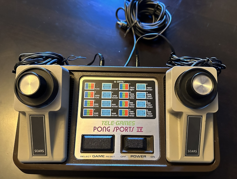
Pong Sports IV is, as the name implies, a four-player game, released under the Atari name as Ultra Pong Doubles. Stuff under the Atari name seems to be a bit rarer than the Sears counterparts, which probably says something about how dominant Sears was in the 1970’s retail scene. Sic transit gloria mundi.
Interestingly, with two paddles plugged in as above, Pong Sports IV’s game options differ from how they are with four paddles plugged in; the console itself only has room for two paddles. The paddles are plugged in using 2.5mm mono headphone jacks.
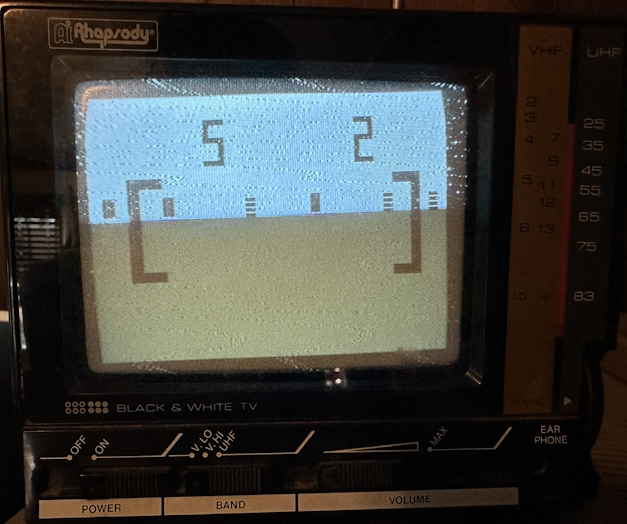
I have two paddles set up because there’s just one Nicole. What’s that, you say? Pong doesn’t have a one-player mode? Au contraire! Just take a look at the initial Home Pong manual.
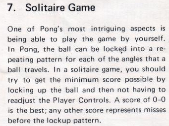
If I am playing Pong in a solitaire fashion, that 5-2 isn’t very good. But enough of that. Let’s crack this thing open.
Atari Inside (tm)
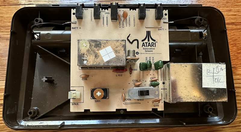
Pong Sports IV comes from an era in which the United States Federal Communications Commission (FCC) was notoriously strict about RF emissions. Surprisingly, Atari didn’t enclose the whole circuitboard in a box; instead, the RF and the single-chip Pong IC are each in their own smaller metal boxes. Above are the array of ports, including a “battery eliminator”. (This one is 6V; don’t use an Atari 2600 9V power cable– UPDATE: Chupperson on Mastodon told me that the very similar Atari Ultra Pong Doubles did in fact use a 9V “battery eliminator” identical to that of the 2600; not sure, but all I can say is I stuck with the 6V power supply for this post)
The goal is to create an AV output with composite video. You’ll notice that the speaker is internal, so only three input wires go into the RF modulator. Power (which we’ll discuss) and ground, and finally, our composite video signal:

Don’t mind the frequency, since this is in single-shot mode. But there are two things to notice:
- The voltage is very low. This signal definitely needs to be amplified, which is typical.
- I had to use AC coupling to get this nice signal; otherwise, there was a large DC offset.
So, now we know we need a video amplifier. It’s traditional in composite mods to build a simple amplifier out of transistors, but in this case, I’m going to use a professional part, the TI THS7316. This is a very solid amplifier that’s pretty popular in the enthusiast community, but sadly comes only in surface-mount packages. As we’ll see, I’m using some adapters for that.
But first, let’s take a look at the data sheet.
Some video DACs or encoders are not referenced to ground but rather to the positive power supply. These DACs typically only sink current rather than the more traditional current sourcing DAC where the resistor is referenced to ground. The resulting video signals can be too high of a voltage for a dc-coupled video buffer to function properly. To account for this scenario the THS7316 incorporates a sync-tip clamp circuit. This function requires a capacitor (nominally 0.1 μF) to be in series with the input. Note, while the term sync-tip-clamp is used throughout this document, it should be noted that the THS7316 is better termed as a dc-restoration circuit based on how this function is performed. This circuit is an active clamp circuit and not a passive diode clamp function.
This sounds like what might be happening with our Atari signal. So essentially, to get the AC coupling we want, we just need a 0.1uF capacitor on the input. Why, TI even gives us a diagram, showing not only what we need to provide, how the polarity should be set, and also the internal amplifier circuit.

Note that this isn’t a true AC coupling, and there’s a more complex circuit described later. But let’s not bother with that for now.
Unfortunately, there’s still a problem. See, this is a 6V device. Its power supply actually goes directly across the board (so that crappy power supply really is an issue), there’s no regulator, and the maximum power supply voltage the THS7316 can take is 5.5V. So I don’t really want to run it overpower.
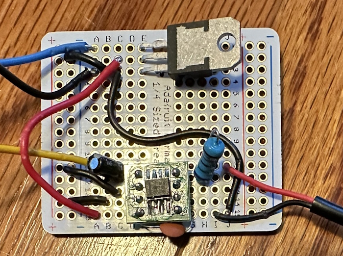
There are a few options here. One of the most common is to use a diode; its 0.7V drop would bring the 6V down to 5.3V, which should be within the safe range. That still felt pretty hot, though, so I decided to use a voltage regulator to bring the 6V down to 3.3V, which this amplifier can also run at. Despite my recent post, I decided to use a linear regulator, the LD1117V33, to produce a nice 3.3V.
Rather than make a full circuitboard and get it made, I just threw together a quick circuit on a solderable breadboard. The three wires going in are blue for power, yellow for video, and black for ground, and an RCA cable tail like that I used on the Odyssey 100 for video.
When installing this in the circuit, for noise reasons, it’s important to have the cables be as short as possible. (You can actually even see noise in my RF photo above) I mounted this on top of the “Atari Innovative Leisure” logo; thank you for leaving that space, Atari. Another thing for noise reasons I had to do was completely depower the RF modulator, which left some convenient places to get the signal I needed.
Video!
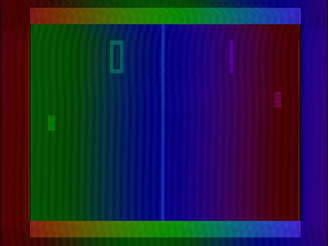
People say a lot of things about Atari in the 1970’s that I certainly am not able to confirm or deny, but what I can confirm is: yeah, it’s supposed to look like that. Well, maybe not that high-frequency noise– possibly should’ve used the THS7314, which has a built-in low-pass filter, though the low-pass filter on the Framemeister didn’t help– but the rainbow colors? Oh yes.
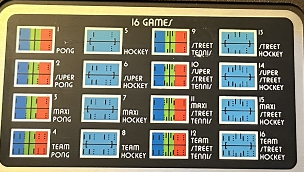
Don’t believe me? Take a closer look at the list of games on the console’s controls. I don’t know why the rainbow isn’t in the same color order, but it’s definitely there.
The pale blue background games are the hockey games, but in reality they’re just as rainbow, but inverted. And as you can see, the hockey goals in Pong Sports IV are more elaborate than the Odyssey 100 or even the Color TV Game 6.
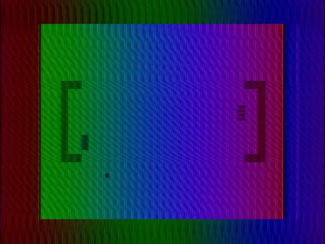
The striped paddles make it clear who is the left player and who is the right player; there are different arrangements of paddles, some with two alternating, some with two on each side, so while it may be obvious here, it can actually be pretty helpful; again, something the competition wasn’t doing.
At first I wondered if the darker areas were proof that my whole signal was too high, and those were supposed to be full black. But I happen to have some screenshots I took with the RF2AV box; the lock-on with that wasn’t reliable at all, but I managed to get some stills at least. It managed to blur out the noise, so some kind of filtering is definitely needed. And the dark areas still have a rainbow.
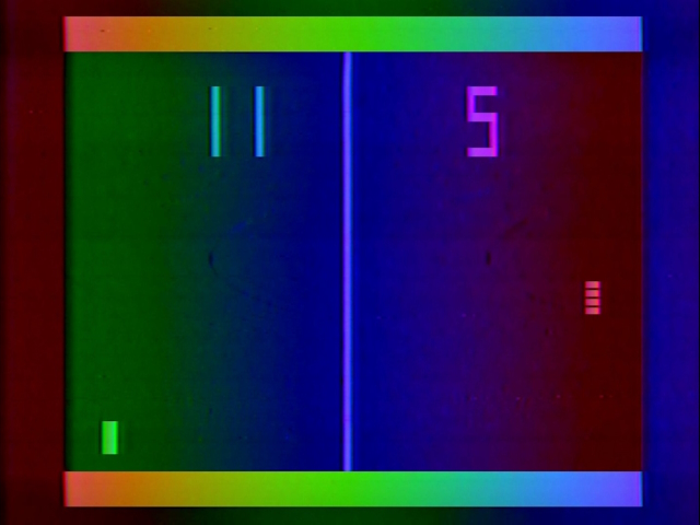
That noise…
But really, that noise is really bad. My first attempt was to add a 100uF capacitor across the 3.3V regulator; I had neglected this initially. I didn’t think this was the cause since the noise seemed correlated with the signal, but was worth a try, and is good practice anyway. But it helped a little bit.
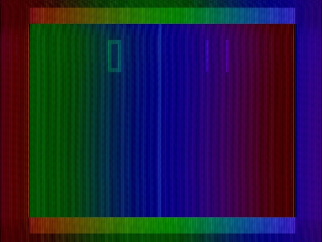
Even actually using the intended 0.1uF capacitor didn’t have the impact I hoped; in fact it may have made things a little more shimmery.
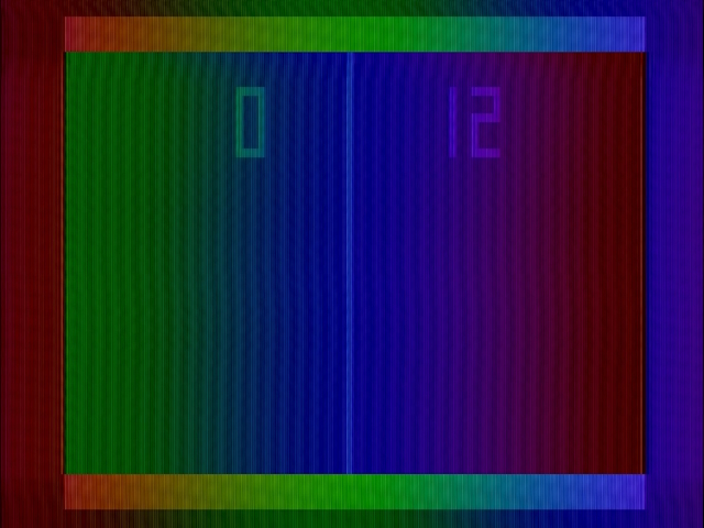
So let’s ignore that for now. Perhaps using a THS7314, but I had some trouble removing the chip I soldered in place, so we’ll leave it be. Let’s instead focus on those rainbow colors. Unlike the noise, those are real, and very much intended.
But how?
So this is interesting; the Atari 2600 is an incredibly colorful console with more shades than even consoles that came well after it, like the NES and the ColecoVision. But this rainbow Pong blows it away. How did Atari do this? Well, of course, it’s a bit of a hack.
If you take a look at the video signal trace above and zoom in, you’ll notice some nice high-frequency noise overlaying the entire signal. Of course, we know that in composite video, the color is a high-frequency signal that overlays the video. Unfortunately those black lines are also a high-frequency trace overlaying the video, so it’s hard to use an oscilloscope.
So let’s ignore that. In any case, in color television, the color information is stored in the phase of the color information. The wave that carries color is always the same frequency, so the television can separate it from our noise.
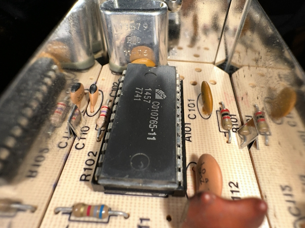
Let’s take a look inside that metal box. All it’s got is the main chip, an Atari C010765-11, some passives, and a crystal. The main IC is socketed, which is pretty neat to see.
The crystal is labeled 03679, with a date of 11/76. Normally, in a usecase like this, you’d see a colorburst crystal, 3.579MHz. But this crystal is slightly off. 3.679MHz. That’s no coincidence.
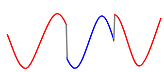
Televisions are designed to have some leeway in the color carrier signal; at the beginning of each line, the colorburst synchronizes the two. But 3.679MHz is too far off. So what does a signal that’s just a bit off look like? It looks like a signal that’s constantly changing in phase!
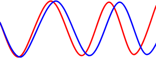
And that’s what Pong Sports IV, as well as the other rainbow Atari Pong games, including Home Pong itself, do. It can invert the signal to provide the color change on the playfield in hockey modes, but not much more than that. On one hand, it has every single color available to NTSC television. On the other hand, is it really color at all?

One more try…
So back in my composite comparison blog post, I noticed that “poor quality” upscalers like the ubiquitous AV2HD boxes actually can do a better job of upscaling the Apple ][, which has a notoriously out of spec signal. High quality upscalers like the Framemeister show odd stripe artifacts, representing the horizontal lines that actually make the color through the NTSC artifacting process. In this screenshot, the horizontal lines are particularly visible in columns 5 and 8.
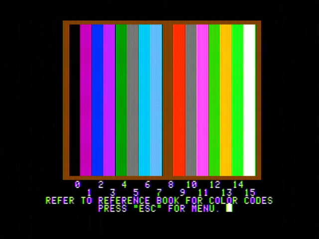
So I took one of those AV2HD boxes– one that was recently used by my wife for Twitch streaming, until I convinced her to use a RetroTink 2X-MINI– and behold:
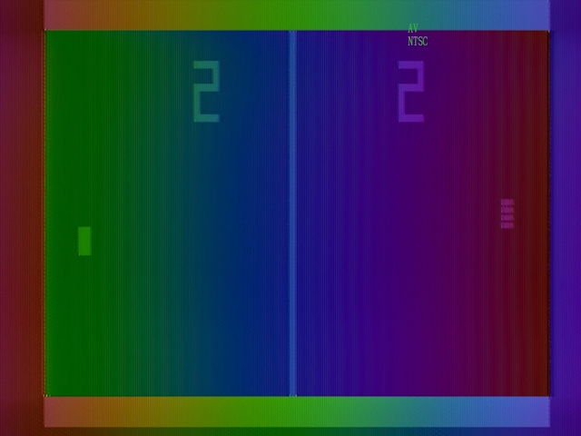
It actually looks pretty decent! I’m not sure, but maybe those lines (still faintly visible) are the same thing as the misinterpreted color signal. Adding more clues is that the horizontal lines invert when the color phase inverts as well. To see what I mean, here’s a zoomed in image from the Framemeister; I’d be curious if anyone has encountered this before and could confirm or explain better.

A series on: Pong consoles
Game consoles that do only one thing. Do they do it well? Eh, debatable.
- First is the Worst: Nintendo's Color TV Game 6 & 15 — Nintendo's take on the Pong console. Surprisingly not great; should they just give up on this whole console thing?
- The Bare Minimum Video Game: The Odyssey 100 — Calling the Magnavox Odyssey 100 a Pong console may be a violation of court order, so be careful-- this hardware's origins predate Pong itself.
- Composite Mod from Scratch: Atari's Pong Sports IV — People make a lot of allegations about life at Atari in the 1970s, but one thing is clear: their Pong consoles sure are colorful. Psychedelic?
- The Last of the First: The Magnavox Odyssey 500 — Ending the Pong console series with a look at the very last console based on the original Magnavox Odyssey. Did you get actual pixel graphics in my Pong?
- The Epoch System 10: The Pong to End All Pongs — One more Pong console to round out 2024. The Epoch System 10 was Epoch's first time making a console with their own R&D, and led directly to their Cassette Vision console. Is it worth the time?

